I got motor control, button inputs and button LEDs working last night. No “intelligence” yet, just getting some modules and functions wired up to test that nerves can talk to all the peripherals.
I’m going to test out talking to the RGB-LEDs and reading the ultrasonic sensor next.
Ooh, that makes me think of the potential for swarms that leverage drafting for reducing collective energy expenditure when traveling together in formation.
Thinking out loud, maybe each bot could continuously monitor the motor’s energy draw when keeping pace as a proxy for wind resistance.
I tried to get the RGB LEDs working last night, but ran into a snag where the pi is not detecting any devices connected to the i2c bus…
iex(4)> Circuits.I2C.detect_devices()
Devices on I2C bus "i2c-1":

0 devices detected on 1 I2C buses
I’m expecting to see a device with address 0x54 based on what I’m seeing in the python library. Not sure how to proceed… but maybe I’ll just skip controlling those leds for now
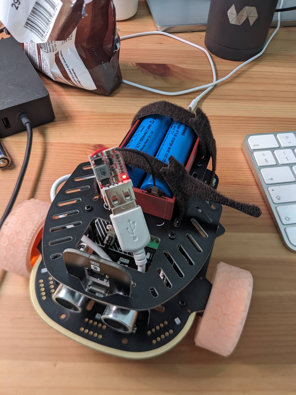
I’ve been on vacation this week and didn’t make much progress, but I did get a little battery case designed and printed, and wired up a pair of old 18650 battery cells from a head torch to work as batteries for the project.
This has been working well and keeps the bot pretty light compared to the battery bank that I had sitting around. I also worked a bit on the ultrasonic sensor, but didn’t get it working. I tried looking at the python code and it seemed to just send a pulse on an output GPIO (to power the ultrasonic speaker?) and then it waited for an input on an inbound GPIO (the receiver pushing a signal?), but after trying this with pullup, pulldown and floating input settings, I never get a reading back on my input pin: trilobot/lib/trilobot/sonic.ex at 3c3814f749848d67d909121f7cbd666ccc63623f · mmmries/trilobot · GitHub
So the motors, buttons and simple LEDs are all working great, but I haven’t been able to detect the RGB LED board via I2C and I can’t get the ultrasonic sensor working. I’m considering re-burning my SD card with just a raspbian install so I can try out the python code samples to see if it that works
Re: The i2c not being detected - have you tried to communicate with the documented address anyway? I think it’s technically possible for the address not to show, but need to confirm.
We also prob need to confirm the frequency used for I2C vs what the device expects.
Booyah! When @jjcarstens jumps into the project you know it’s going to be real good!
I did try sending a few commands to the LED controller, but didn’t get anything to light up. I was also translating a lot of python code to elixir and I’m not sure I was actually assembling the right binary commands. I’ll try to find some documentation around the frequency used to see if that might be the problem too.
I see the I2C commands in the data sheet? (but I had to expand “more pages” to get them). Maybe try setting the shutdown mode to “normal” and see if that succeeds?
I hadn’t seen the “more pages” button, thanks for pointing that out. I filled out a module based on what I saw in the arduino library and it looks like the arduino library writes a 0x01 value to the 0x00 register and calls that a “CMD_ENABLE_OUTPUT”… I hadn’t seen that in my first round of experimentation.
It also looks like the arduino library always sets the PWM channels and then does a final write to the “update” register which seems like a way to tell the chip to update all of its values at the same time?
I’m traveling this week so i can’t test anything until next Tuesday, but if anyone else wants to give it a try it will be interesting to see if my module actually produces any light
I got the LED’s working. The address detection is not a standard so not always supported. Looks like that is the case here for the SN3218 in this setup. But I was able to write to the address and it was a matter of understanding the flow of how it expects to turn on.
You can dump this in IEx and get a little LED spin action with random colors:
{:ok, i2c} = Circuits.I2C.open("i2c-1")

# Docs say this should be 0xA8 (0b10101000), but the python uses
# this address and it works, so ¯\_(ツ)_/¯
addr = 0x54

# Enable LED control
Circuits.I2C.write(i2c, addr, <<0, 1>>)

# I don't know where the LED's are in this control register, so just turn
# them all on - #yolo
Circuits.I2C.write(i2c, addr, <<0x13, 255>>)
Circuits.I2C.write(i2c, addr, <<0x14, 255>>)
Circuits.I2C.write(i2c, addr, <<0x15, 255>>)

loop = fn l ->
  # SN3218 supports 18 LEDs. The Trilobot seems to have 6 RGB leds with
  # each color gamma tied to a single PWM LED register, effectively
  # making the LED control triads of 3 register addresses
  #
  # |        LED         | Red register | Blue register | Green register |
  # | ------------------ | ------------ | ------------- | -------------- |
  # | LIGHT_FRONT_RIGHT  |      1       |      2        |        3       |
  # | LIGHT_FRONT_LEFT   |      4       |      5        |        6       |
  # | LIGHT_MIDDLE_LEFT  |      7       |      8        |        9       |
  # | LIGHT_REAR_LEFT    |      10      |      11       |        12      |
  # | LIGHT_REAR_RIGHT   |      13      |      14       |        15      |
  # | LIGHT_MIDDLE_RIGHT |      16      |      17       |        18      |
  for led <- 1..6 do
    # SN3218 has auto incrementing register addresses. This just means
    # we calculate the first register (red) and then write 3 bytes which
    # will write 1 byte to the 3 registers, starting with the initial (red)
    reg = led * 3
    rgb = for _ <- 1..3, do: Enum.random(0..255)
    # Adjust the PWM for each RGB of LED N
    Circuits.I2C.write(i2c, addr, [reg | rgb])

    # Apply all the settings
    Circuits.I2C.write(i2c, addr, <<0x16, 1>>)

    # Little sleep gives a rotating effect on trilobot
    :timer.sleep(100)
  end

  l.(l)
end

# Don't block our IEx
led_spin = spawn fn -> loop.(loop) end
Thanks for posing Jon! That’s super encouraging. And thanks for the comments in your code, really helpful to know how the 18 channels get mapped into the 6 LEDs.
I’ll be back home on Tuesday and I can’t wait to play around a bit with the Trilobot
It feels a little too-small to make it it’s own hex package, but hopefully these modules are pretty re-usable if anyone wants to drop them into another Nerves Project
I wanted to create an easy way to hook up the button inputs to any custom functionality that people might want for their Trilobots. So I made use of the property_table library which is already part of Nerves and added a commit to makes it easy to write a process that subscribes to button change events.