Circuiits.UART problems in RPI0

Hello,

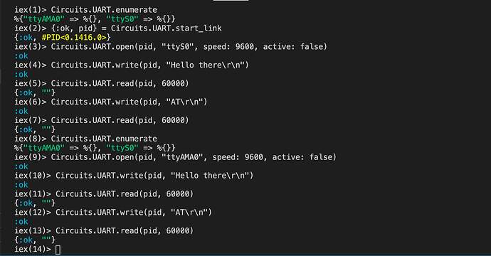
I have been doing tests with Circuits.UART without result and without receiving any communication in ttyS0 or ttyAMA0

It seems that in Raspberry Pi Z the default port associated with GPIO 14 and 15 serial communication is ttyS0 and what worked for me on raspbian was to disable the console service of the ttyS0 port by stopping the service with sudo systemctl stop serial-getty@ttyS0.service and remove the line console = serial0,115200 from cmdline.txt

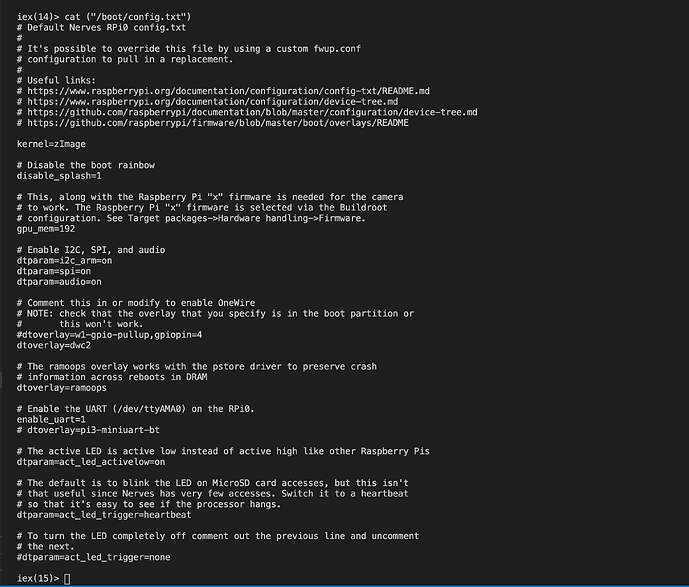
I have also seen in Nerves that in “config.txt” it is overlaying ttyAMA0 on ttyS0 with dtoverlay = pi3-miniuart-bt so that the GPIO serial port is ttyAMA0.

According to the documentation that I have read to use serial communication over GPIO without problems it is necessary to deactivate the console through raspi-config .

https://spellfoundry.com/2016/05/29/configuring-gpio-serial-port-raspbian-jessie-including-pi-3-4/)

I have tried to modify cmdline.txt and config.txt removing the overlap dtoverlay = pi3-miniuart-bt and console=serial0,115200 editing the files directly on my MicroSD but it seems to affect how ssh communications are being mapped so I have not been able to log back in with ssh. If I undo the modifications by ssh circuits@ip or via USB ssh circuits@nerves.local I can log back into the system.

So I don’t know where to continue testing.

I think the key is to disable the serial port console, is there any way in nerves to stop this service or run sudo systemctl stop serial-getty@ttyAMA0.service for the ttyAMA0 port?

I have serial comm working over ttyAMA0 with nerves rpi0 out of the box - so give that a try…
afaik there shouldn’t be any need to change things around…

Hi @outlog. Thanks for the encouragement, I have used the example methods of the official documentation, without result. I am trying to send AT commands to a NB-IoT module connected via GPIO serial pins. But my little experience with Elixir and Nerves is making it very difficult to debug what is happening with the communication. Some sample use of the ttyAMA0 or some method to debug the port will be of great help.

check the wiring first and foremost - also ensure you have solid connection on the wires eg not flimsy breadboarding etc.
(also check that the wires are crossed correctly eg. nerves rx is connected to device tx and vice versa - of course except for those boards that try to be helpful by flipping the rx/tx - sic!)

start out in active mode… ssh to the nerves system and try:

{:ok, uart_pid} = Circuits.UART.start_link
Circuits.UART.open(uart_pid, "ttyAMA0", speed: 9600,active: true)

change the speed to whatever the device is communicating…

enter flush in the console to see received messages (since you are in active mode)

then send a command to the device eg:
Circuits.UART.write(uart_pid, "\xfe\x04\x00\x03\x00\x01\xd5\xc5" )
(obviously change the command to something relevant to device…

and do a flush again to see received messages…

find the datasheet for the device - and especially also find multiple arduino/python libs and find one where the code and commands are obvious and understandable…

I’ve attached code below that I use for a Senseair S8 (co2 sensor)… not cleaned up at all and far from perfect - sorry - I see it even has other irrelevant code for talking with a renogy solar controller lol…

but hopefully it can inspire/encourage you… do pls post more about the device etc. and any code that materializes…

wip code example senseair S8:
It’s started in application.ex in the supervision tree eg:

    children = [
       {Fw.Senseair, %{name: "sensor_1", tty: "ttyAMA0", speed: 9600, blynk: "blynk", virtual_pin: 5}},
       ...
      ]

the module itself…


defmodule Fw.Senseair do
  @moduledoc """
  Documentation for Senseair.
  """
  use GenServer, restart: :permanent #, max_restarts: :infinity

  require Logger

  defstruct name: 0,
            uart_pid: 0,
            co2: []
  
  @name "sensor_1"

  @tty "ttyAMA0"
  @speed 9600

  @target Fw.Application.target()

  @s8_co2            "\xfe\x04\x00\x03\x00\x01\xd5\xc5" 
  # returns <<254, 4, 2, 1, 147, 236, 217>>
  # 1 * 256 + 147 => 403 ppm CO2
  

  @s8_fwver          "\xfe\x04\x00\x1c\x00\x01\xe4\x03" 
  # returns <<254, 4, 2, 1, 79, 237, 64>>
  # "Firmware: %d.%d", buf[3], buf[4]); eg: 1.79


  @cmd_read_CO22      "\xFE\x44\x00\x08\x02\x9F\x25" # returns  <<254, 68, 2, 1, 147, 236, 217>> calc same as s8_co2
  
  @s8_id_hi          "\xfe\x04\x00\x1d\x00\x01\xb5\xc3" # returns <<254, 4, 2, 7, 36, 175, 15>>
  @s8_id_lo         "\xfe\x04\x00\x1e\x00\x01\x45\xc3"  # returns <<254, 4, 2, 84, 44, 146, 57>>

  @cmd_read_RH       "\xFE\x44\x00\x14\x02\x97\xE5"    # returns  <<254, 68, 2, 6, 7, 250, 134>> (256 * 6 + 7 ) / 100 => ~15% (not real, internal?) 
  @cmd_init          "\xFE\x41\x00\x60\x01\x35\xE8\x53" # NOT TRIED
  
  
  # special command 0x7C - param: 0x6 - CO2 background calibration 0x7 - CO2 zero/nitrogen calibration
  @reset_cali_ack          "\xFE\x06\x00\x00\x00\x00\x9D\xC5"
  @start_cali       "\xFE\x06\x00\x01\x7C\x06\x6C\xC7" #NOT TRIED
  # wait at least 2 secs - read_cali_ack should return 1 (20 in hex)
  @read_cali_ack          "\xFE\x03\x00\x00\x00\x01\x90\x05" # returns  <<254, 3, 2, 0, 0, 172, 80>>

  @read_abc_duration  "\xFE\x03\x00\x1F\x00\x01\xA1\xC3" # returns <<254, 3, 2, 0, 180, 172, 39>> (256*0+180) => 180 hours /24 =>  7,5 days
  # set abc not included see hardware(fw) issue https://github.com/letscontrolit/ESPEasy/issues/759
  

  #NOT WORKING?
  @cmd_read_Temp     "\xFE\x44\x00\x12\x02\x94\x45" #returns <<254, 68, 2, 0, 0, 184, 228>>  (256*0+0) ZERO
  
  @cmd_read_det_Temp  "\xFE\x44\x00\x0A\x02\x9E\x45" # returns <<254, 68, 2, 10, 89, 126, 126>> (10*256+89)/100 => 26.49 TOO HIGH internal temp?
  
  @cmd_read_Temp2     "\xfe\x04\x00\x04\x00\x01\x64\x04" # returns <<254, 132, 2, 242, 241>> error?


#iex(19)> data = "\xFE\x44\x00\x08\x02\x9F\x25"
#<<254, 68, 0, 8, 2, 159, 37>>
#iex(20)> data_size = byte_size(data) - 2
#5
#iex(21)> <<head::binary-size(data_size), rest::binary>> = data
#<<254, 68, 0, 8, 2, 159, 37>>
#iex(22)> calc_crc = CRC.crc(:crc_16_modbus, head)
#9631
#iex(23)> << big, small >> = rest
#<<159, 37>>
#iex(24)> rec_crc = big + small*256
#9631
#iex(25)> head
#<<254, 68, 0, 8, 2>>
#iex(26)> rem(9631, 256)
#159
#iex(27)> div(9631, 256)
#37


  # Public Interface

  def start_link(args = %{name: name, tty: tty, speed: speed}, opts \\ []) do
    registry_name = via_tuple(name)
    GenServer.start_link(__MODULE__, {args, name}, name: registry_name)
  end

  defp via_tuple(name) do
    {:via, Registry, {:uart_registry, name}}
  end

  def read_co2() do
    #change to?
    GenServer.call(via_tuple(@name), {:read_co2, @target})
    #GenServer.call(via_tuple(@name), "read_co2")
  end

  def test() do
    GenServer.call(via_tuple(@name), "read_co22")
  end

  def read_raw(data) do
    GenServer.call(via_tuple(@name), {"read_raw", data})
  end


  # GenServer Callbacks

  def init({%{tty: tty, speed: speed}, name}) do
     # stop other pids on same port
     Circuits.UART.find_pids() 
     |> Enum.filter(fn {_, port} -> port == tty end) 
     |> Enum.each(fn { pid, _ } -> Circuits.UART.stop(pid) end)

     {:ok, uart_pid} = Circuits.UART.start_link
     #rx_framing_timeout: 200
     Circuits.UART.open(uart_pid, tty, speed: speed,active: false)
     {:ok, %__MODULE__{ name: name, uart_pid: uart_pid }}
  end

  #host testing
  def handle_call({:read_co2, target}, _from, state) when target == :host do
    co2 = 400

    data = %{co2: co2, time: DateTime.now!("Europe/Copenhagen")}
    {:reply, {:ok, co2}, Map.put(state, :co2, [data | state.co2]) }
  end

  #real
  def handle_call({:read_co2, target}, _from, state) do
    Logger.info(inspect(@s8_co2))
    Circuits.UART.write(state.uart_pid, @s8_co2)
    
    result = case Circuits.UART.read(state.uart_pid, 1000) do
      {:ok, read_values} -> read_values
      _ -> nil
    end
    
    if correct_crc?(result) do
      co2 = case result do
        <<254, 4, 2,  big, small, _crc1, _crc2>> ->
          co2 = big *256 + small
        _ -> nil
      end
      {:reply, {:ok, co2}, state}
    else
      {:reply, {:error, "unable"}, state}
    end
  
  end

  def handle_call("read_co22", _from, state) do
    if Fw.Application.target() == :host do
      IO.inspect("host")
    end

    # copy/paste string from manual
    #"01 03 000C 0008 840F" 
    #|> String.replace(" ", "") 
    #|> String.codepoints 
    #|> Enum.chunk_every(2) 
    #|> Enum.map(&Enum.join/1) 
    #|> Enum.reduce(<<>>, fn x, acc -> acc <> Base.decode16!(x) end)

    #raw = "\x01\x03\x01\x01\x00\x01\xD4\x36"  #voltage battery
    #raw = "\x01\x03\x00\x14\x00\x04\x04\x0D" # giver <<1, 3, 8, 0, 1, 3, 0, 0, 0, 5, 0, 134, 116>>
    raw = "\x01\x03\x00\x0C\x00\x08\x84\x0F" # model name

    Circuits.UART.write(state.uart_pid, raw)
    
    result = case Circuits.UART.read(state.uart_pid, 1000) do
      {:ok, read_values} -> read_values
      _ -> nil
    end

    result2 = case Circuits.UART.read(state.uart_pid, 1000) do
      {:ok, ""} -> result
      {:ok, read_values} -> result <> read_values
      _ -> <<>>
    end

    result3 = case Circuits.UART.read(state.uart_pid, 1000) do
      {:ok, ""} -> result2
      {:ok, read_values} -> result2 <> read_values
      _ -> <<>>
    end

    Logger.info(inspect(result))
    Logger.info(inspect(result3))
    
    if correct_crc?(result3) do
      co2 = case result3 do
        <<1, 3, 2, 0, voltage, _crc1, _crc2>> ->
          voltage/10
        <<1, 3, x, tail :: binary>> -> # model name
           <<head::binary-size(x), rest::binary-size(2)>> = tail
           String.trim(head)
        _ -> nil
      end
      {:reply, {:ok, co2}, state}
    else
      {:reply, {:error, "unable"}, state}
    end
  
  end


  def handle_call({"read_raw", data}, _from, state) do
    Logger.info(inspect(data))
    Circuits.UART.write(state.uart_pid, data)

    read = Circuits.UART.read(state.uart_pid, 1000)
#
    Logger.info(inspect(read))
#
    #result = case read do
    #  {:ok, read_values} -> read_values
    #  _ -> nil
    #end
    #if correct_crc?(result) do
    #  {:reply, {:ok, result}, state}
    #else
    #  Logger.info("result:#{inspect(result)}")
    #  {:reply, {:error, "raw_unable"}, state}
    #end
    {:reply, {:ok, "wrote_raw"}, state}
  end

  # handle any unknow calls
  def handle_call(msg, _from, state) do
    Logger.info("Unknown handle_cast msg: #{inspect msg}")
    {:reply, "unknown call message", state}
  end

  # for active mode NOT USED HERE
  def handle_info({:circuits_uart, _tty, data}, state) do    
    Logger.info("Got data on serial:#{inspect data}")
    {:noreply, state}
  end

  defp correct_crc?(data) when data == nil or data == "" do
    false
  end

  defp correct_crc?(data) do
    data_size = byte_size(data) - 2
    <<head::binary-size(data_size), rest::binary>> = data 
    << big, small >> = rest
    CRC.crc(:crc_16_modbus, head) == big + small * 256
  end


end
Hello @outlog , thank you very much for your help and encouragement.

I have tried to use your example, I got no results, through serial GPIO. I have also tried to emulate the same setup that works for me in python ttyS0 as miniUART modifying in Nerves cmdline.txt and config.txt to see if I could leave the original configuration and deactivate the serial console, which is what the manufacturer indicates. But also without result in Nerves. I’ll try to get a logic analyzer to see if I get something on serial GPIO pins. And try to see what encoding is using nerves in the sending and receiving of text strings.

Although I will also try instead of porting from python to Elixir the entire library. I will try to do the setup by USB port and microusb cable. And try using ppp protocol, with Vintage Net Mobile as a Custom Modem. Which I think will be more compatible with the entire Nerves and Nerves Hub environment for the distribution of Firmware, which is the final goal. Although I’m still trying to put all the pieces of the puzzle together and see which is the best setup.

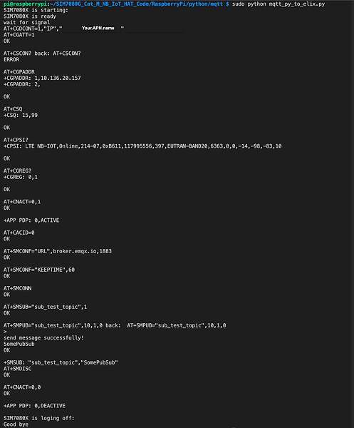
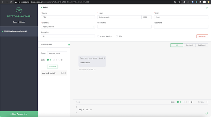
The example code in python for mqtt communication and the results of the tests is:

The result is the same as nerves default setup, in active mode the same, flush does’t give any result:

Python sample code:

import RPi.GPIO as GPIO
import serial
import time

ser = serial.Serial('/dev/ttyS0',9600)
ser.flushInput()

power_key = 4
rec_buff = ''
Message = 'SomePubSub'

def power_on(power_key):
    print('SIM7080X is starting:')
    GPIO.setmode(GPIO.BCM)
    GPIO.setwarnings(False)
    GPIO.setup(power_key,GPIO.OUT)
    time.sleep(0.1)
    GPIO.output(power_key,GPIO.HIGH)
    time.sleep(2)
    GPIO.output(power_key,GPIO.LOW)
    time.sleep(2)
    ser.flushInput()
    print('SIM7080X is ready')

def power_down(power_key):
    print('SIM7080X is loging off:')
    GPIO.output(power_key,GPIO.HIGH)
    time.sleep(2)
    GPIO.output(power_key,GPIO.LOW)
    time.sleep(2)
    print('Good bye')
    
def send_at(command,back,timeout):
    rec_buff = ''
    ser.write((command+'\r\n').encode())
    time.sleep(timeout)
    if ser.inWaiting():
        time.sleep(0.1)
        rec_buff = ser.read(ser.inWaiting())
    if rec_buff != '':
        if back not in rec_buff.decode():
            print(command + ' back:\t' + rec_buff.decode())
            return 0
        else:
            print(rec_buff.decode())
            return 1
    else:
        print(command + ' no response')

try:
    power_on(power_key)
        print('wait for signal')
        time.sleep(10)
    send_at('AT+CGDCONT=1,"IP","Your.APN.name"','OK',1)
    send_at('AT+CGATT=1','OK',1)
    send_at('AT+CSCON?','OK',1)
    send_at('AT+CGPADDR','OK',1)
    send_at('AT+CSQ','OK',1)
    send_at('AT+CPSI?','OK',1)
    send_at('AT+CGREG?','+CGREG: 0,1',0.5)
    send_at('AT+CNACT=0,1','OK',1)
    send_at('AT+CACID=0', 'OK',1)
        send_at('AT+SMCONF="URL",broker.emqx.io,1883','OK',1)
        send_at('AT+SMCONF="KEEPTIME",60','OK',1)
        send_at('AT+SMCONN','OK',5)
        send_at('AT+SMSUB="sub_test_topic",1','OK',1)
        send_at('AT+SMPUB="sub_test_topic",10,1,0','OK',1)    
    ser.write(Message.encode())
    time.sleep(10);
    print('send message successfully!')
    send_at('AT+SMDISC','OK',1)
    send_at('AT+CNACT=0,0', 'OK', 1)
    power_down(power_key)
except:
    if ser != None:
        ser.close()
        GPIO.cleanup()

if ser != None:
        ser.close()
        GPIO.cleanup()

The python code works!!

I will post if I have any result with the logic analyzer or by ppp setup and Vintage Net Mobile.

my guess would be that you are not doing the powering “on” off the device on gpio 4 which the python code does - don’t know the specs but assume you need to replicate the def power_on(power_key): with https://github.com/elixir-circuits/circuits_gpio

eg something like: (check if 4 is correct pin - they sometimes have different
{:ok, gpio4} = Circuits.GPIO.open(4, :output)

and then a oneline

Circuits.GPIO.write(gpio4, 1); :timer.sleep(2000); Circuits.GPIO.write(gpio4, 0);

depending on specs, maybe use pullup/down eg Circuits.GPIO.set_pull_mode(gpio, pull_mode)

keep us posted on any progress…

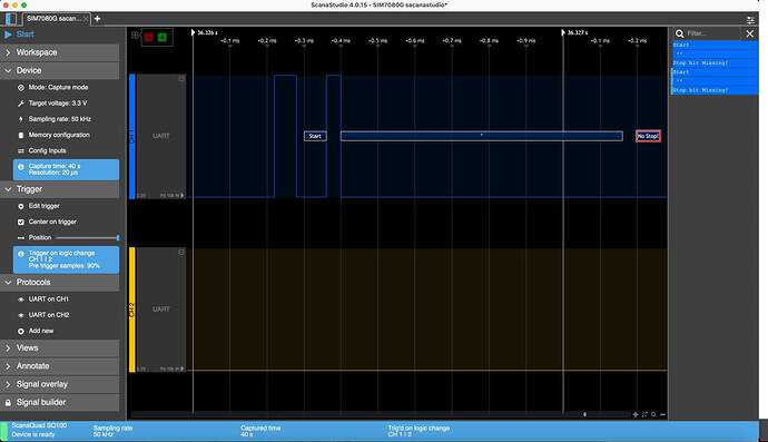
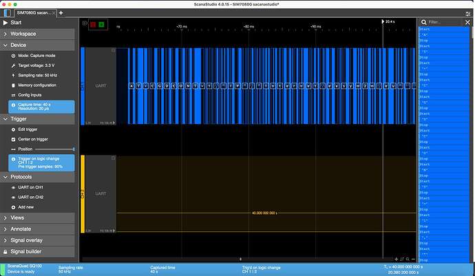
It would have been fun and easy to solve if was this, justo to power on. I’m afraid it will be something more complex. With the logic analyzer the only thing I get after having turned on the board with Circuits.GPIO or with the physical button on the board. They are unreadable frames sent every so often without any specific action since I have a trigger that launches the recording when there is movement in the Tx or Rx and I only get start and stop bit missing! even without performing any action on the port. However in python the port is stable and only receives data when I receive or send data, and AT commands are correctly decoded in ASCII.

Logic Analyzer in Nerves. Channels setup Tx GPIO pin on blue in Phyton and Nerves tests.

And the example in python decoding every AT command, and launching the trigger when send the command.

I’ll post more test of the results.

1 Like