
Lucassifoni
Configuring PWM channel outputs on the Allwinner D1 (MangoPi MQ Pro)
Hello dear Nerves users,
I’m trying to get a PWM output to show up on the 40-pin header on the MangoPI, specifically physical pin 35, or GPIO 38 as seen from Elixir. My goal is to have a few PWM channels physically available on the header to control them with the sysfs (/sys/class/pwm) interface.
To summarize :
- I think I found the relevant information in the D1 manual.
- I’m pretty sure I do not know how to properly apply it.
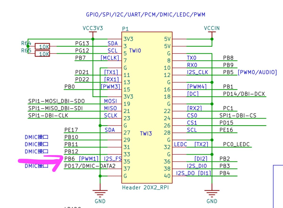
I found the following pin multiplexing table in the official D1 documentation (beware : 1300+ pages)

Further, since this pin should be handled by PB6, I found the relevant register address :

And the bit pattern to configure PB6 to use the PWM1 channel :

My understanding is that I should be able to get the PWM1 channel on PB6 / GPIO38 by setting the register at address 0x02000000 + 0x0030 to the bit pattern 000001010000000000000000 or 0x050000 (since PB6_SELECT is set by using the bits 27 to 24).
I found samples of DTS files online for similar purposes that I tried to modify, some compiling, and some not, but none having any tangible effect towards my goal.
I would greatly appreciate any direction on that matter. Am I looking at the wrong level of abstraction by thinking in terms of bit patterns and registers, and pinmux configuration is instead done at a slightly higher level ?
Best,
Lucas
Most Liked

ConnorRigby
I know it’s been a while since you posted this, but just in case you haven’t figured it out, or if anyone else stumbles upon this in the future, here’s a example of enabling a PWM channel on the t113s. Pwm by ConnorRigby · Pull Request #1 · ConnorRigby/nerves_system_underglow3 · GitHub
it should be the same on the D1. The source file for pinctrl will be in here Making sure you're not a bot!
Lucassifoni
Hey ! If someone does need the PWM outputs of the mangopi to actually come out on the header, you can checkout my branch here : GitHub - Lucassifoni/nerves_system_mangopi_mq_pro at pwm-ability · GitHub
Here is a dynamic overlay that correctly muxes the pins, on top of the 6.18.36 kernel update : nerves_system_mangopi_mq_pro/pwm-7ch-overlay.dts at pwm-ability · Lucassifoni/nerves_system_mangopi_mq_pro · GitHub
For ease of use, you can checkout my two helper libraries, DtsBuddy and Pwmx, described here : Two helper libraries, DtsBuddy and Pwmx
Here is how to get leds blinking on the exposed channels in an iex session :
iex(livebook@nerves.local)1> import DtsBuddy.Sigil
DtsBuddy.Sigil
iex(livebook@nerves.local)2> DtsBuddy.enable_overlays
:ok
iex(livebook@nerves.local)3> DtsBuddy.overlays_enabled?
true
iex(livebook@nerves.local)4> compiled =
  ~DTS"""
  /dts-v1/;
  /plugin/;
  &{/soc/pinctrl@2000000} {
    pwm0_pb5:  pwm0-pb5  { pins = "PB5";  function = "pwm0"; };
    pwm1_pb6:  pwm1-pb6  { pins = "PB6";  function = "pwm1"; };
    pwm2_pb11: pwm2-pb11 { pins = "PB11"; function = "pwm2"; };
    pwm3_pb0:  pwm3-pb0  { pins = "PB0";  function = "pwm3"; };
    pwm4_pb1:  pwm4-pb1  { pins = "PB1";  function = "pwm4"; };
    pwm5_pd21: pwm5-pd21 { pins = "PD21"; function = "pwm5"; };
    pwm7_pb10: pwm7-pb10 { pins = "PB10"; function = "pwm7"; };
  };
  &{/soc/pwm@2000c00} {
    pinctrl-names = "default";
    pinctrl-0 = <&pwm0_pb5>, <&pwm1_pb6>, <&pwm2_pb11>, <&pwm3_pb0>,
                <&pwm4_pb1>, <&pwm5_pd21>, <&pwm7_pb10>;
    status = "okay";
  };
  """pwm7ch
{:ok, "/data/pwm7ch.dtbo", "pwm7ch"}
iex(livebook@nerves.local)5> DtsBuddy.load(compiled)
:ok
iex(livebook@nerves.local)6> DtsBuddy.status("pwm7ch")
:applied
iex(livebook@nerves.local)7> Pwmx.list_available_outputs()
[
  {"pwmchip0", 0},
  {"pwmchip0", 1},
  {"pwmchip0", 2},
  {"pwmchip0", 3},
  {"pwmchip0", 4},
  {"pwmchip0", 5},
  {"pwmchip0", 6},
  {"pwmchip0", 7}
]
iex(livebook@nerves.local)8>
outs = for ch <- [0, 1, 2, 3, 4, 5, 7], into: %{}
  {:ok, pid} = Pwmx.Output.start_link({"pwmchip0", ch})
  pid |> Pwmx.Output.set_period(500_000, :us) |> Pwmx.Output.set_duty_cycle_absolute(250_000, :us)  |> Pwmx.Output.enable()
  {ch, pid}
end
- PWM5 on header pin 11
- PWM0 on header pin 12
- PWM3 on header pin 15
- PWM4 on header pin 16
- PWM1 on header pin 35
- PWM2 on header pin 31
- and PWM7 on pin 29 all work
 .
.
Lucassifoni
Thanks a lot for these resources, I should be able to leverage them. I’ve put the project on the backburner for a while, but should be getting to it quite soon.
It’s also very nice to have that kind of samples for more advanced topics on the forum ![]() .
.
Popular in Questions


Other popular topics


 Latest Nerves Threads
Latest on Elixir Forum
Sponsor Spotlight

Courses that'll move you from confusion to "Aha, now I get it!"
Categories:
Sub Categories:
Forums
Popular Tags
- #ecto
- #liveview
- #troubleshooting
- #learning-elixir
- #deployment
- #library
- #erlang
- #testing
- #genserver
- #mix
- #absinthe
- #remote-other
- #otp
- #plug
- #how-to-question
- #macros
- #postgres
- #channels
- #elixirconf
- #exunit
- #discussion
- #code-sync
- #javascript
- #podcasts
- #onsite
- #dialyzer
- #docker
- #authentication
- #umbrella
- #full-time-contract
- #podcasts-by-brainlid
- #ecto-query
- #elixir-ls
- #phoenix_html
- #iex
- #blog-post
- #graphql
- #genstage
- #ai
- #websockets
- #supervisor
- #elixirconf-us
- #advent-of-code
- #distillery
- #processes
- #forms
- #api
- #metaprogramming
- #security
- #hex
Our Sponsors

Build Elixir applications with speed and confidence.

Supporting innovation across the BEAM ecosystem.

We build reliable cloud platforms for business-critical systems.

Catch errors, track performance, monitor hosts and more.

Error tracking for Elixir devs who love to ship. Start your free account.

Practical resources that improve the lives of professional developers.

Producing high quality Elixir screencasts since 2017.

Enabling companies to succeed by building software people love.

The team behind Membrane, Popcorn, LiveDebugger. Available for hire.
Courses that'll move you from confusion to "Aha, now I get it!"