Using TMF8821 time-of-flight sensor for navigation

This is part of the toy_robot group. Some of us are playing around with using Nerves to control small robots and specifically this thread will be about trying to use the TMF8821 sensor to detect objects in front of our robot for the purposes of navigation.

I’m planning to build on the excellent work of Powell Kinney who implemented GitHub - pkinney/tmf882x

3 Likes

Sparkfun has some helpful resources for this sensor:

The key things to know about this sensor are that it uses a low power laser to sense distance of objects in front of the sensor. It uses some clever techniques to actually measure a grid of distances. There are some tradeoffs between how many measurements there are in the grid and how big the field of view is. I’m planning to use the built-in 3x3 configuration which samples distances 30x per second which should be able to detect both white and dark objects in bright sunlight at a distance of ~750mm.

Screenshot 2023-09-04 at 17.06.50

1 Like

Initially I’m hoping to get the sensor connected and use it to handle a basic wandering algorithm. Something that tends to drive in circles and drive forward when there’s nothing in the way.

Eventually I would love to implement something like a simultaneous localization and mapping algorithm to keep sensor readings over time and build up a map of the area around the robot and also use that to figure out where the robot currently is within that map

1 Like

One thing I’ve been running into is how to connect the TMF8821 to my Trilobot. The bot connects to all 40 pins of the raspberry pi, and only exposes a few of them via through-holes that you can solder into.

I looked into re-using the connector for the ultrasonic sensor, but that sensor if 5V based so the trilobot ads voltage conversion on the trigger pin and the echo pin. There are plenty of soldering points for just the I2C bus and we could use poling from the GitHub - pkinney/tmf882x library, but I was hoping to make use of the triggering GPIO which will notify the raspberry pi when a new measurement is ready rather than constantly asking the sensor for a new measurement.

Maybe I should just start with polling to get the sensor working rather than agonizing over a performance detail at this point of the project?

Does it use a voltage regulator? I would assume it uses a 5V rail from the 5V pin of the pi. I’ll have to inspect it closer later.

For the sensor, there is always the option to solder it on the reverse side nubs on the bottom of the pin that’s sticking up :smile:

I’m looking for trilobot schematics to see if there is something to shim on there. Since there is a spacer set of pins, I think we could shove something between them for worse case

1 Like

What kind of package you have? From what I see in the datasheet of TMF8821, the connection is done via a flex cable, not to the main gpio pins.

Definetly :joy: .

1 Like

Pimoroni is great in offering engineering drawings and an electronics schematic: https://cdn.shopify.com/s/files/1/0174/1800/files/trilobot_schematic.pdf?v=1639566970

It looks like maybe the trigger GPIO is not being adjusted to 5v? It seems to pass straight through to the sensor, but the “echo” line goes through a voltage divider which I think is a simple way to adjust the 5v signal down to a safe voltage for the pi?

That jump would be convenient to use a removable connector, but it doesn’t have any I2C lines. So maybe I should start by using one of the i2c connector points and just use that to solder wires straight to the sensor? I can still make a rigid mount for the sensor once I need more accuracy in the measurements, but a straight soldered connection would make it easy to get started and I don’t need the trigger GPIO pin for getting started.

O I misread. Are you trying to leave the ultrasonic sensor out and just reuse that connector for this TMF8821?

I did end up manually tracing the INT pin on all the extra I2C breakouts around the board where you can solder more. Looks like they are all on the same line and go to GPIO 4. Though if you’re replacing the ultrasonic, then the QWIIC connector could power the TMF8821 and connect I2C and you could use the US_TRIG line as an interrupt

:man_facepalming: oh man, that makes complete sense to use the QWIIC connector. I didn’t even think about that even though both the trilobot and the sparkfun board clearly have those connectors on them.

That is obviously a good way to have an easily re-usable connection. I don’t have any of those cables, but I’m sure I can find one

I got my qwiic conector cables and the device worked immediately. The hex package currently depends on I2C 1.x so I have to override that to 2.x which seems to work fine.

I was able to set a configuration and read some values, but I have no idea how to interpret the values I got back so far :laughing:

iex(14)> config = TMF882X.get_config(pid) |> Map.put(:spad_map_id, 7)
%{
  period: 33,
  alg_setting_0: %{distances: true, logarithmic_confidence: false},
  confidence_threshold: 6,
  gpio_1: %{gpio: 0, driver_strength: 0, pre_delay: 0},
  gpio_2: %{gpio: 0, driver_strength: 0, pre_delay: 0},
  hist_dump: false,
  i2c_addr_change: 0,
  i2c_slave_address: 65,
  int_persistence: 0,
  int_threshold_high: 65535,
  int_threshold_low: 0,
  int_zone_mask_0: 0,
  int_zone_mask_1: 0,
  int_zone_mask_2: 0,
  kilo_iterations: 537,
  osc_trim_value: 12,
  power_cfg: %{
    allow_osc_retrim: false,
    goto_standby_timed: false,
    keep_pll_running: false,
    low_power_osc_on: false,
    pulse_interrupt: false
  },
  spad_map_id: 7
}
iex(15)> TMF882X.put_config(pid, config)
:ok
iex(16)> config.spad_map_id
7
iex(17)> TMF882X.start_measuring(pid) 
:ok
iex(18)> TMF882X.stop_measuring(pid) 
:ok
iex(19)> flush()
{:tmf882x,
 %TMF882X.Result{
   tid: 241,
   size: 128,
   number: 237,
   temperature: 20,
   valid_results: 23,
   ambient: 6502,
   photon_count: 1657586,
   reference_count: 56528,
   sys_tick: 124164633,
   measurements: [
     {101, 255},
     {100, 255},
     {104, 255},
     {115, 255},
     {118, 255},
     {113, 255},
     {113, 255},
     {116, 255},
     {0, 0},
     {110, 255},
     {109, 255},
     {110, 255},
     {113, 255},
     {119, 255},
     {117, 255},
     {113, 255},
     {112, 255},
     {0, 0},
     {0, 0},
     {0, 0},
     {0, 0},
     {0, 0},
     {0, 0},
     {0, 0},
     {0, 0},
     {0, 0},
     {0, 0},
     {0, 0},
     {545, 56},
     {563, 62},
     {582, 31},
     {590, 109},
     {586, 255},
     {601, 255},
     {625, 98},
     {0, 0}
   ]
 }}

I think I may have figured out what’s going on. The datasheet has a little information blurb on page 27

So when I was getting back these measurements that seemed to have randomly mixed 0’s measurements, I wasn’t sure how to interpret them, but it seems that there are some “gaps” in the zones. So I need to skip the 9th measurement returned and then stitch them back together to get the zones as they are displayed in the datasheet diagram

It’s working! I have it sampling 10x per second and then I take zones 6,7, 10 and 11 (in the middle) and wire them up to the front 2 RGB LEDs so that they get dim when it senses something close. This will give me a visual indication of what the bot thinks that it sees ahead.

3 Likes

Now that I have my sensor talking to nerves, there are two follow-up items I need to address:

  1. Update the tmf882x project to use circuit_gpio v2+
  2. Mount the sensor in a reliable way to the trilobot

The first project can be all done in software and involves learning fun new things like how to do host-based testing of an I2C interface, but I’ve been programming all week for work. So I’m going to do the obviously wrong thing and start with project 2

The first thing I noticed is that the Trilobot “leans back a little”, so I put it on a flat surface and measured that the front of the trilobot is about 1cm higher than the back. And since I can’t be bothered to look up the trig I learned back in high school, I just drew a quick sketch in onshape and asked it to measure the angle for me.

Screenshot 2023-09-23 at 15.10.43

Then I grabbed the cad model I had previously made of the Trilobot and copied out the “front board” part, removed the holes for the ultrasonic sensor, and added a tilted face with this same angle.

Screenshot 2023-09-23 at 15.13.31

Then I sketched in the mounting holes based on the TMF8821 datasheet that shows the location of the 3 mounting holes, and cut out those holes from the model.

Screenshot 2023-09-23 at 15.14.57

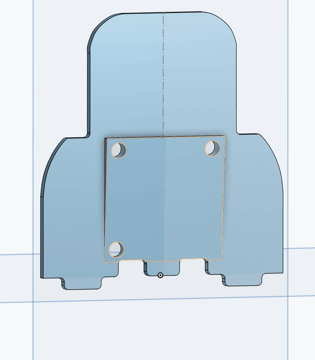
Exported this to 3mf, sliced it and sent it to my 3d printer. We’ll see in 30min if it fits :crossed_fingers:

3 Likes