How do we create a UML Class Diagram for Elixir Phoenix App?
1 Like
Of all UML diagrams the class diagrams makes little to no sense in functional programming as there is no inheritance. So what for you need such diagram? What are your expectations out of it?
3 Likes
You don’t. Elixir has no classes ![]()
But UML is so much more than only classes…
4 Likes
Yea I understand. But how do I document in UML the modules and contexts including the functions?
I am wondering how would that be @NobbZ and @hauleth
I actually need to create a diagram for the elixir modules and contexts
and at the same time create a sequence diagram for a phoenix app hmmm
I don’t know about the usefulness of UML in Elixir-land, but if your goal is to create some kind of high-level visualisation of your system, then perhaps one approach might be to create a simple network diagram, where each node in the network represents a process and the lines between the nodes represent the messages that said processes use to communicate with each other.
Another approach which might be a good fit, could be to create some kind of swimlane diagram where each swimlane represents a process (actor) in your system and the boxes within the swimlanes represent the different tasks (activities) that are performed by each process.
One thing I have found to be particularly difficult when creating diagrams of Elixir and Erlang applications is their highly concurrent nature. Many things are happening at the same time. I find it difficult visualize concurrent applications with two-dimensional diagrams, because it’s difficult to convey how things are not happening in a predictable and sequential order.
I suppose the “best” choise of visualisation depends on who will use the visualisation and for what purpose. What is the purpose of the diagram you want to create?
4 Likes
Ah, yes! Just like that.
I didn’t know about that command! Very useful.
Thanks for asking this question. As a solution architect I do a lot of drawing, but I rarely use UML anymore. After I get my domain analysis done I prefer Freemind for describing code at a high level, and then I expect the code to do the rest.
This is a snippet from a supply chain management solution I’ve been working on:
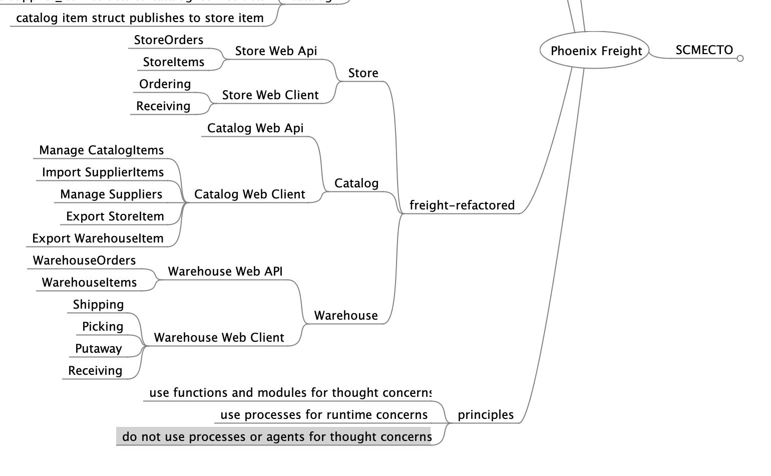
Since this is an agile community, I am wondering what others do when they need to draw their ideas for the team. I would love to see some examples.
5 Likes
I tend to use:
- sequence diagram - for describing workflow of a particular feature
- entity relationship diagram - for describing tables/foreign keys, but also sometimes structs
- tree diagram (name?) - for describing supervision
3 Likes
I’ve found sequence diagrams invaluable in helping product owners recognize and clarify ambiguities in feature descriptions. (Easy to write and generate via PlantUML.)
2 Likes
If you’re a Mac user then Sequence Diagram (Mac App Store and web site) is really good and I like the fact that you construct the diagrams via plain text.
1 Like
I’ve had pretty good success with PlantUML.
3 Likes
I’ve found https://www.draw.io to be pretty useful for all sorts of diagrams.
For sequence diagrams, et is your friend ![]()
It comes already inside OTP, there’s a nice talk that shows a bit of it (at 25min): https://www.youtube.com/watch?v=CozSfI-Zepw&feature=youtu.be&t=1505
5 Likes